Download This File
Download
All Documents
Go to
Home Page
Chapter
10
Virtual
Circuits and Channels
Or
How
to Interconnect OmniBoxes
A
Virtual Channel is one that is not
associated with a digital span timeslot or a loop current device (Analog line)
at loading time, but one that is created at runtime assuming either the physical
parameters of a real channel or those of a Virtual Circuit. A Virtual Circuit is
anything that can convey a voice bit stream between to distant points, these
Virtual Circuits will allow to connect Virtual channels in different OmniBoxes.
Virtual
channels are not just for remote routing, they can also perform Call-Back
in the inbound channel that received the trigger, do inbound/outbound
through the same channel and blind test calls in any channel.
Remote
Connection of Two Real Channels
The
SC (or H.100) Bus
Before
we go any further, it is important to understand how two channels in two
different spans are connected through SC Bus because the principles involved in
the connection of virtual channels in different OmniBoxes are very much the
same.
 The
SC bus, that is the 26 lead gray ribbon cable that connects all the ISA Dialogic
boards, has 1024 timeslots. The
H.100 Bus, used by the newer PCI boards, has
4096 timeslots. The difference is just capacity, but in both cases you may
regard the timeslots in these busses as a being virtual wires through which you
may send sound bit streams. For simplicity, we will refer to any of these busses
as the H.100 Bus.
The
SC bus, that is the 26 lead gray ribbon cable that connects all the ISA Dialogic
boards, has 1024 timeslots. The
H.100 Bus, used by the newer PCI boards, has
4096 timeslots. The difference is just capacity, but in both cases you may
regard the timeslots in these busses as a being virtual wires through which you
may send sound bit streams. For simplicity, we will refer to any of these busses
as the H.100 Bus.
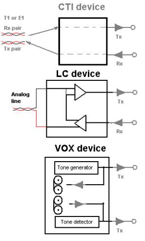
OmniBox
deals with three types of bus devices: digital channels (DTI) , loop current
(LC) and voice resources (VOX). Each of these devices has a transmitting and a
receiving port that can connect to other devices through the H.100 bus.
The
Dialogic driver connects a timeslot to each device’s transmitting port when
the service starts. These assignments are fixed and can’t be changed by an
application at runtime, however, the Receiving ports may be set at runtime to
“listen” to any timeslot (TS from now on) in the H.100 bus.
Assume
a system with a D/240SC-2T1 (48 DTI and 24 VOX) with ID 0 and a D/41ESC.(4 LC
and 4 VOX) with ID 1 The fixed assignments will go as follows:
-
TS
0-23 will be assigned to the VOX of the D/240SC-2T1
-
TS
24-27 will be assigned to the VOX of the D/41ESC
-
TS
28-75 will be assigned to the DTI of the D/240SC-2T1
-
TS
76-79 will be assigned to the LC of the D/41ESC
-
TS
80 to 1023 if SC or 4095 if H.100 are free.
Lets
consider the routing of a successful call from the third channel in the first T1
(Ch103) to, say, the fifth channel in the second T1 (Ch 205) .
To receive the digits, dial out and to monitor the call progress the 7th
voice resource will be used. Ch 103 transmits in TS 30, Ch 205 in TS 56 and the
VOX in the TS 6.
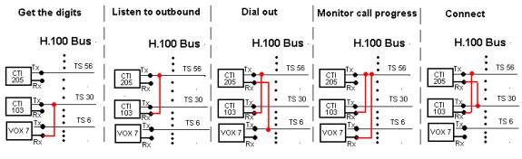
*in
this example the D/240SC-2T1 is an ISA legacy board that uses the SC Bus, not
the H.100.
Virtual
Channels (VC’s) may “assume” real channels physical parameters (the TS
among others). You are going to
need that for Call-Back services and two-way traffic where calls are required to
be placed in channels defined as inbound
A
VC may also represent one in a remote OmniBox connected through virtual
circuits. Hereafter, we will refer to this type of VC as a Remote Channel or RM.
In the case of Remote Channels there is no “assuming”. If you need to route
a real channels into a remote one, you will need to assign one of the free
timeslots in the H.100 bus to this virtual channel the same way the Dialogic
driver assign timeslots for real devices. You may not create more remote
channels that there are free timeslots in the H.100 bus. Parameter 19 for Set_ID
= 0 in the sys_Parameter table, sets the Virtual Circuit Array size, it
must be less than the bus size minus total device count or:
ArraySize
<= TS count – CTI channel count + LC channel count + VOX count
For
the example above ArraySize <= 1024 – 48 – 4 – 28 =
1024 – 80 = 944 . Of course, if all the virtual channels are to be
remote, even if all the real channels were defined as inbound, you’ll never
need more than 52, so there’s no need to make virtual channel array greater
than this.
There
are a few technologies that can establish virtual circuits (VC’s), between
switches, namely: ATM, VoIP, Fiber optic TDM, Ethernet packets, etc. All these
technologies, no mater how different in principle of operation, have one common
feature, there is always a capacity or max VC count. Lets call this limit VCMAX
and, no matter what technology is to be used, the virtual circuits available
will be numbered from 0 – (VCMAX-1).
To
route a call from a remote Virtual Channel in OmniBox1 to another in OmniBox2,
you will need one VC each to transmit into. This VC’s must not be used by any
other connection until the call is over, so a means must be provided to organize
the use of these virtual circuits.
There’s
the static way, you assign them in the same manner Dialogic driver does, for
instance, virtual circuits for OmniBox1 will take VC’s from 0 to 199, OmniBox2
from 200 to 399…and so on. It’s simple but makes an inefficient use of the
capacity since in no switch all the channels are being used all the time.
The
best use of the capacity is when you assign the VC’s dynamically. For this you
need a central VC distributor, when you need to place a call in a remote
channel, a VC is requested to the VC distributor and it will give you a free VC,
that from this moment on will be “In Use”. When the call is over, the VC is
return to the distributor and its status is set to “Free” again. This way it
is guaranteed that if there’s no VC for a call, it is that they are all “in
use” and not just “assigned” as with the static way.
To
be able to handle calls through Virtual Circuits, there must be a way of setting
them up and controlling its progress. This problem is very similar to that
Common Channel Signaling or CCS, like ISDN or SS7. Since the problem is similar,
the solution should be similar too, hence, OmniBox uses a protocol in the same
spirit of the one used for ISDN described in the ANSI specification Q.931, only
simpler.
As
in the ISDN protocol the Remote Call Protocol (RCP) will have a Call setup
message and also the call Proceeding, alerting connect, disconnect and release
complete. Also drop causes will follow the Q.931 specs but there’s where the
similarity ends. The messages and Elements IE. are not binary but textual and
are sent over IP an not a DS0. The port number and the IP address of the socket
to send and receive these protocol messages must be set in the ParamNumValue
and ParamStrValue fields of the sys_Parameter table respectively
with ParamID = 20.
Here
is a detailed description of the messages:
Call
setup is the “O” message (OFFERED) :
<Message
Size>O o:<outbVCh> t:<VC num> r:<Local
Range>
i:<Orig
Domain> d:<DNIS> a:<ANI>
This
message is set from originator to terminator, the IE’s are:
<Msg
Size> Three
numerical digits expressing is the character count of the message
without
including those three. This IE will be found leading all messages.
<Outb
VCh> Virtual channels
get a channel number as they are created, this
information
element is the number of the outbound VCh originating the
remote
call. It will do as a CRN (Call Reference Number) for the
originating
OmniBox, in other words, every message sent back to the
originating
OmniBox must carry this reference.
<VC
Num> This
is the Virtual Circuit number that the VC distributor gave to the
originating
OmniBox to transmit into. The OmniBox receiving this
message
must create an inbound Virtual Circuit and have this VC talk
into
the H.100 bus timeslot assigned to it.
<Local
Range>This is the outbound trunk group that connects to the desired
destination,
The
receiving OmniBox must find a free outbound channel in that range
To
place the requested call.
<Orig
Domain>This is a string that will identify the originating inbound trunk
group
and the originating OmniBox as well. I has
the format:
<Eng>_<Domain
Name> for example Domain “Client1” in OmniBox
number
3 will be expressed in this information element as “3_Client1”.
This
string will show in the call detail information text box of the
OmniMonitor
to the right of the remote inbound channel number that
will
show as negative to highlight its virtual nature.
<DNIS>
<ANI> The DNIS will be used as the
number to be dialed (no further digit
processing
will be done) and the ANI is the originating phone number to
be
passed along to the setup of the call in the real outbound channel.
The
“P” message or call PROCEEDING.
<Msg Size>P o:<outb VCh> i:<inb
VCh> t:<VC num>
This
message is sent from terminator to originator as a call setup acknowledge, the
IE’s are:
<Msg
Size> Same
as above
<Outb
VCh> The CRN, the
reference so that the originator can figure out which call is
this
message referencing.
<Inb
VCh> The
CRN that will reference this call in the terminating OmniBox (the one
sending
this message) Any further messages from the originator regarding
this
call must refer to this number. The inbound virtual channel number is used as
the call CRN.
<VC
num> Is
the Virtual Circuit number given by the VC distributor to the
inbound
virtual channel. This VC will be listening to the Tx timeslot of the
real
outbound channel. The originating Virtual channel, upon reception of
this
message, must route this VC into its assigned H.100 timeslot.
The
“A” message (ALERTING.)
<Msg Size>A o:<outb VCh>
This
message is sent from terminator to originator to signify call acceptance (not
answer supervision), this normally after a ring is detected or an ALERTING
message is received, the IE’s are:
<Msg
Size> Same
as above
<Outb
VCh> The CRN, the
reference so that the originator can figure out which call is
this
message referencing.
The
“C” message (CONNECT)
<Msg Size>A o:<outb VCh>
This
message is sent from terminator to originator as Answer Supervision
notification, the IE’s are:
<Msg
Size> Same
as above
<Outb
VCh> The CRN, the
reference so that the originator can figure out which call is
this
message referencing.
The
“D” message (DISCONNECT)
<Msg Size>D o:<outb or inb
VCh> c:<Cause>
This
message may be sent by either the terminator or originator to notify a hang up,
the IE’s are:
<Msg
Size> Same
as above
<Outb
or inb VCh>The CRN that suits the notified. If the called party hung-up, it
is the
terminator
that must notify the originator and thus, the CRN is the
originator’s
outbound virtual channel number In
case of the calling party
hanging
up, the notification goes originator to terminator and the CRN
would
be the inbound virtual channel number in the terminator.
<Cause>
References the Q.931 standard causes for disconnection. (See
appendix A)
The
“R” message (RELEASE COMPLETE)
<Msg Size>R o:<outb or inb
VCh> c:<Cause>
This
message may be sent by either terminator or originator to acknowledge a
DISCONNECT message , the IE’s are:
<Msg
Size> Same
as above
<Outb
or inb VCh>The CRN that suits the notified, same as above
<Cause>
Returns the same cause as received in the DISCONECT message
Every
OmniBox that is to be involved in remote connections must have one
virtual inbound trunk group or Virtual Domain (VD), to which all inbound
remote channels will belong. Also, when a call is setup in a real channel, but
its dialed string corresponds to a destination that is only available through
another OmniBox, the routing will point to a Virtual Range (VR). Domains
and Ranges have properties that are common to all its member channels, many of
these properties don’t make sense for virtual ones and also there are
properties for virtual channels that can’t be applied to real ones. Virtual
trunks group parameters will be found in the same tables of the real ones, dia_InCh
and dia_OutCh. They must also be listed in the dia_GroupDefs table
with ChCount field set to 0 (The value of ChMin must be 0 too for
the Virtual Domain).
In
the case of the Virtual Domain, you may simply ignore the properties
related to digit processing, routing, the watchdog or the hung-trunk detector,
also, the accounts issue is irrelevant, you may use any account or a bogus one,
if you like to be consistent with its irrelevancy. The only fields in the dia_InCh
table that play a roll are: DomainID; Description (Trunk Name) and Function that
must be set to 4.
The
Virtual Range case is slightly more complicated. First, there can be any
number of VR’s in an OmniBox and second is that not only the watchdog,
digit processing, idle time, mode mask and Provider fields won’t apply, but
that there are remote specific properties that must me stored in the same dia_OutCh
table, so a different set of meanings to the fields must be defined for the
virtual case.
Field
Meanings for the dia_OutCh table
|
Field
|
Real
Ranges
|
Virtual
Ranges
|
|
Field
0
|
RangeID
|
RangeID
|
|
Field
1
|
Description
|
Description
|
|
Field
2
|
OutHunting
|
IP1
|
|
Field
3
|
MinIdleTime
|
IP2
|
|
Field
4
|
EndWithPound
|
IP3
|
|
Field
5
|
Provider
|
IP4
|
|
Field
6
|
Outbounf
Mode Mask
|
Remote
Port
|
|
Field
7
|
ExchProcSet
|
Remote
Range ID
|
|
Field
8
|
WD_MaxGrpBadInARow
|
Remote
Engine
|
|
Field
9
|
WD_MaxChBadInARow
|
Irrelevant
|
|
Field
10
|
WD_SampleSize
|
Irrelevant
|
|
Field
11
|
WD_MinCompletion
|
Irrelevant
|
|
Field
12
|
WD_BalanceChOffSet
|
Irrelevant
|
|
Field
13
|
WD_ShortsAreBad
|
Irrelevant
|
|
Field
14
|
WD_RecheckMins
|
Irrelevant
|
Explanation
of the new meanings:
IP1.IP2.IP3.IP4
: The
4 components of the IP address of the OmniBox where the
Remote
Range is.
Remote
port :
Is the port number of the socket that will attend the in the Remote
Call
protocol in the remote OmniBox
Remote
Range ID:
The value of the RangeID field in the remote OmniBox.
Remote
Engine:
The Engine number of the Remote OmniBox.
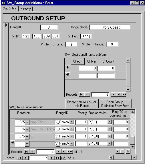
The
utility OmniBoxSetup.mdb provides special entry form for virtual Ranges:
A
real inbound channel is seized and the dialed digits collected. The digits
happen to correspond to a route with its top priority being a Virtual
Remote Range (VRR), a Remote Call (RC) must be placed
through a Virtual Channel (VCh) of that VRR. A VCh doesn’t
exist until it is created so, we must request the VRR to
create a VCh that inherits its properties (IP, Remote port, Remote Range
etc.). This creation process also involves the assignment of a free H.100
timeslot and a Virtual Circuit (VC) from the VC distributor. The
real inbound channel is then routed full duplex to this virtual channel, in
other words, the inbound channel will be set to listen o the free TS just assign
to the VCh and the given VC set to listen
to the Tx TS of the real inbound channel.
For
the sake of the example, lets put some numbers here, starting with the inbound
call lets assume that:
-
the
real inbound channel is 103;
-
belonging
to Domain with group ID=6 named Client1;
-
the
number dialed was 01122541234567,
-
which
after stripping and translating, turned into just 41234567
-
the
ANI to be sent is 7185671234
The
VCh just created say, is the 5th in that OnmiBox, which lets
say, is Engine number 4. The VCh’s are numbered on a 0 basis, so this
one will be VCh(4). The VRR happened to be the one named Ivory Coast with
group ID=3 and its properties were:
-
IP
123.456.789.001,
-
 Remote
port 5001,
Remote
port 5001,
-
Remote
range 9,
-
Engine
8.
Finally
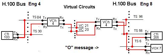
assume the given VC was number 20. From all these numbers, we can figure
that channel 103 Tx TS is 30, the free TS assigned to the VCh, being the
5th, is number 84, so channel 103 will be set to listen to TS
84.
Now
the VC is requested to make the RC (Remote Call, as you had probably
forgotten), that starts by sending the following
“O” message to port 5001 at IP 123.465.789.001 :
050O
o:4 t:20 r:9 i:4_Client1 d:41234567 a:7185671234
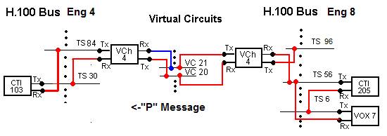
Now,
Engine 8, receives the “O” message, next, it must requests its Virtual
Domain to create an inbound VCh. Lets assume it is the 17th
or that VCh(16) is created. If we further assume, for simplicity, that
both OmniBoxes have the same type and count of boards, the VCh(16) will
have the H.100 TS 96 to have it listening to VC(20). VCh(16) will
also need a VC to transmit into, so it must request one from the VC
distributor. It has not been long since Engine 4 requested its VC, so,
assuming its free, it is likely that the VC distributor assigns the next VC
in line, namely VC(21).
Provided
all the data from the “O” message has been properly received, the
procedure to place a call in the requested range is started and the “O”
message is acknowledged by replying with the following “P” message.
015P
o:4 i:16 t:21
When
Engine 4 receives the “P“ message, the routing is completed. The H.100 TS 84
will be set to listen to VC(21) and VC(20) will be set to listen to H.100 TS 30
(remember? The one channel 103 transmits into). Now it waits for further call
progress messages from Engine 8.
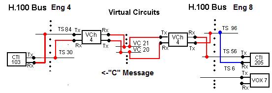
Back
in Engine 8, an available channel, say the 205, was found in Range 9, VC(21)
is set to listen to H.100 TS 56 (205 transmits into TS 56)
and the number 41234567 has been dialed, VOX(7) is waiting for a
ring. Got a ring!, actually, the caller in channel 103
heard that ring too (Ch(205)->ts56->VC(21)->ts84->Ch(103)).
Now the following “A” message is sent to Engine 4 to stop the “dead air”
timer and start the “no answer” one.
005A
o:4
VOX(7)
is waiting again, this time for a voice, a FAX or a recording… Got a voice!,
Caller at Ch(103) heard “Hello…”, next the reverse sound path is
established, Ch(205) is set to listen to H.100 TS 96 that’s listening VC(20)
that was listening to H.100 TS 30 where Ch(103) transmits. From this moment on,
the called party will hear when the callers says “Linda, Hi!, long time no
talk…”. Also, a “C”
message must be sent to Engine 4 to “officially” notify that it can start
charging Mr. Caller in channel 103.
005C
o:4
Back
again in Engine 4, when the C message is received the answer supervision signal
is sent through Ch(103) back to the seizing switch. Now all the channels, Engine
4 and 8, virtual and real are in a connect state.
This
particular example call is not going to be a long one and though it will have a
normal ending it is not be happy one. What Mr. Caller hears next is Linda saying
“…and you have the nerve of calling me after all this time…” and then a
busy signal, after a couple of useless “Linda…Linda?”, he must hang up
too.
This
is what went on in the OmniBoxes:Ch(205) gets a DISCONNECT event when Linda
hangs up, lets assume that it is set up, not to truncate by sending a DISCONNECT
message to engine 4 but just to play a Busy Signal. This is accomplished
by having VC(21) listen to H.100 TS 0 (the voice resource that
plays the busy in an OmniBox can be either VOX(1) or VOX(2) depending on what
was played first, a ring or a busy, we have just assumed it was VOX(0) that
transmits in TS 0).
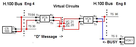
When
Mr. Caller, after losing all hope, hangs up, a disconnect event is received in
Ch(103), the call is truncated, this is the inbound call is dropped and the VCh(4)
sends a “D” message:
011D
o:16 c:16
The
o:16 is addressing VCh(16) in Engine 8 while c:16 is the Q.931
cause code that means NORMAL CLEARING. At
Engine 8, when receiving this, the call is be dropped at Ch(205) and after
sending the “R” message and releasing VC(21) with the VC
distributor, the VCh(16) is destroyed.
010R
o:4 c:16
Back
at Engine 4, when the “R”
message is received VC(20) is released with the VC distributor and VCh(4)
is destroyed and this is the end of Mr. Caller call to Linda
To
set up a Call-Back service, a DNIS service with as many phone-numbers as clients
will be needed. Each client will be given one of the mentioned phone-numbers to
which he or she must call to get a call back from the service. In the OmniBox,
the Domain doing the Call-Back service will have its function set to dynamic by
DNIS or -1 (See dia_InCh table description in Chapter 4). It is in the DNISLookup
table where the Call-Back ServFunction
number (13) must be set, together with the Call-Back phone number in Str2.
This Call-Back phone-number, must match the Account
of the Call-Back client’s account registry in the Balances table (See Balances
table description in Chapter 4). The cost rate of the call-back call in
field Float1 and the mode mask (See
dia_OutCh table description in Chapter
4) for the outbound call in the Num2
field. An example of a Call-Back entry in the DNISLookup table:
|
Dnis
|
ServFunct
|
Str1
|
Str2
|
Num1
|
Num2
|
Description
|
Float1
|
|
2548304
|
13
|
|
5821473456
|
|
0
|
Test
|
.20
|
OmniBox
perfoms the Call-Back in the same channel that attends the trigger call.
As it is the normal way in Call-Back, the trigger call will never be
answered, the program will wait until the caller hangs up or for a 20 second
timeout to expire, whatever happens first.
Now,
a Virtual Outbound Channel (the VCh)
will be created by a Virtual Range (VR)
with the same group ID as the Domain to which the inbound channel attending the
call belongs. This VCh will be an
outbound but will assume the physical
properties of the inbound. Exactly, the assumed properties are those specified
in the span’s cdp file and also the assuming VCh inherits the ownership
of any voice resource that the assumed channels might have had.
Assuming
the example case, OmniBox will make up to three attempts to 5821473456 at 10
seconds interval, if a connection is achieved, the Virtual Channel will
“Un-assume” the inbound channel, in other words, everything will behave from
that moment on, as if the call-back had been an inbound call. The Long Distance
IVR state machine (See Chapter 4)
will take it from there prompting the caller for a destination phone number…
Etc.
After the Call-Back client is done with service, the VCh resources are
freed.
A
Virtual Range with ChCount = 0 and ChMin = 0,
as we have seen is a VRR or a one to be used in Remote Calls. If ChMin
is <> 0, then is not remote but one “Associated” to a Domain, the one
with its ID equal to the ChMin value.
OmniBox recognizes logical channels only as inbound or outbound, but this
virtual channel concept allows physical channels to work both as inbound and
outbound, thus allowing channels to act as two way trunks.
When
a call needs to be routed to a VR with association to a Domain, OmniBox will
search for a free channel in it, then have the VR create a VCh and make it
assume the physical properties of the free inbound channel (same as with the
Call-Back) but in this case, even the channel number will be assumed, so that
the monitor can better display the details of the call that will be placed in
this VCh. When the call is over, the VCh will be destroyed.
For
Two Way trunks the original meanings of the parameters in the dia_OutCh
table, will make sense again. Everything will operate the same, only that
physical channels belong to a REAL inbound trunk group or Domain.
WARNING:
Since the dia_GroupDefs table may have more than one record per trunk
group, it is possible to enter ChCount = 0 in one, making it Virtual, and
then make it different than zero in another making it also Real. This is not
acceptable for OmniBox, trunk groups must be either REAL or VIRTUAL. A trunk
group can not have a part that is virtual and also a few channels that are real.
* NOTE: Not all cause values are
universally supported across switch types.
Before a particular cause
value is used, its validity should be
compared
with the appropriate switch vendor specs.
|
UNASSIGNED_NUMBER
|
0x01
/* Cause 01 */
|
|
NO_ROUTE
|
0x02/*Cause02*/
|
|
CHANNEL_UNACCEPTABLE
|
0x06/*Cause06*/
|
|
NORMAL_CLEARING
|
0x10/*Cause16*/
|
|
USER_BUSY
|
0x11/*Cause17*/
|
|
NO_USER_RESPONDING
|
0x12/*Cause18*/
|
|
NO_ANSWER_FROM_USER
|
0x13/*Cause19*/
|
|
CALL_REJECTED
|
0x15/*Cause21*/
|
|
NUMBER_CHANGED
|
0x16/*Cause22*/
|
|
DEST_OUT_OF_ORDER
|
0x1B/*Cause27*/
|
|
INVALID_NUMBER_FORMAT
|
0x1C/*Cause28*/
|
|
FACILITY_REJECTED
|
0x1D/*Cause29*/
|
|
RESP_TO_STAT_ENQ
|
0x1E/*Cause30*/
|
|
UNSPECIFIED_CAUSE
|
0x1F/*Cause31*/
|
|
NO_CIRCUIT_AVAILABLE
|
0x22/*Cause34*/
|
|
NETWORK_OUT_OF_ORDER
|
0x26/*Cause38*/
|
|
TEMPORARY_FAILURE
|
0x29/*Cause41*/
|
|
NETWORK_CONGESTION
|
0x2A/*Cause42*/
|
|
ACCESS_INFO_DISCARDED
|
0x2B/*Cause43*/
|
|
REQ_CHANNEL_NOT_AVAIL
|
0x2C/*Cause44*/
|
|
PRE_EMPTED
|
0x2D/*Cause45*/
|
|
FACILITY_NOT_SUBSCRIBED
|
0x32/*Cause50*/
|
|
OUTGOING_CALL_BARRED
|
0x34/*Cause52*/
|
|
INCOMING_CALL_BARRED
|
0x36/*Cause54*/
|
|
BEAR_CAP_NOT_AVAIL
|
0x3A/*Cause58*/
|
|
SERVICE_NOT_AVAIL
|
0x3F/*Cause63*/
|
|
CAP_NOT_IMPLEMENTED
|
0x41/*Cause65*/
|
|
CHAN_NOT_IMPLEMENTED
|
0x42/*Cause66*/
|
|
FACILITY_NOT_IMPLEMENT
|
0x45/*Cause69*/
|
|
INVALID_CALL_REF
|
0x51/*Cause81*/
|
|
CHAN_DOES_NOT_EXIST
|
0x52/*Cause82*/
|
|
INCOMPATIBLE_DEST
|
0x58/*Cause88*/
|
|
INVALID_MSG_UNSPEC
|
0x5F/*Cause95*/
|
|
MANDATORY_IE_MISSING
|
0x60/*Cause96*/
|
|
NONEXISTENT_MSG
|
0x61/*Cause97*/
|
|
WRONG_MESSAGE
|
0x62/*Cause98*/
|
|
BAD_INFO_ELEM
|
0x63/*Cause99*/
|
|
INVALID_ELEM_CONTENTS
|
0x64/*Cause100*/
|
|
WRONG_MSG_FOR_STATE
|
0x65/*Cause101*/
|
|
TIMER_EXPIRY
|
0x66/*Cause102*/
|
|
MANDATORY_IE_LEN_ERR
|
0x67/*Cause103*/
|
|
PROTOCOL_ERROR
|
0x6F/*Cause111*/
|
|
INTERWORKING_UNSPEC
|
0x7F/*Cause127*/
|
*The Cause value greater than127 is
allowed to define here. There is
No conflict with those universal
defines which ranges 0-127
Download This File
Download
All Documents
Go to
Home Page