The analog world used the reversed battery signaling and the E & M (4 wire system for PBX extensions) signaling to indicate seizures, acknowledgements and even to do pulse dialing. The E & M scheme uses two extra leads for the signaling information the ‘E’ lead, or the Ear lead, the receiving lead and the ‘M’ lead or Mouth lead, the transmitting lead. When an extension goes off hook, the ‘M’ lead’s potential goes to Power Supply and the ‘E’ lead to ground. When back to On Hook ‘M’ goes to ground and ‘E’ goes open. To emulate the E & M leads, the digital approach had to provide two bits, they were called the ‘A’ and ‘B’ bits. Since no more bits could be added to the stream, the designers decided to “steal” a couple of bits from the data in a super frame:
the 8th bit of every time slot in the 6th frame of every super frame will be regarded as the signaling bit ‘A’ of that time slot;
the 8th bit of every time slot in the 12th frame of every super frame will be regarded as the signaling bit ‘B’ of that time slot.
This would hardly have any effect on the sound and would provide for the necessary signaling.
Digital PBX’s use signaling protocols involving both bits but most of the inter-switch communications use only the ‘A’ bit or ‘A’ and ‘B’ in a mirror fashion.
The idle state value for the signaling bits is something that is part of the handshake protocol and can be set in any of the four different possibilities but the general usage is that idle => A = B = 0.
The simplest handshake is the one called “Immediate Start”. Say Switch 1 is setting up a call on Switch 2. Switch 1 sets it Bit ‘A’ to 1, this meaning seizure for Switch 2, which gets ready to receive the dialing digits. After a guard time, Switch 1 sends the digits. Switch 2 attempts connection, if successful it raises its ‘A’ bit meaning connection acknowledge or Answer Supervision. If called party hangs up, Switch 2 loses connection and lowers it ‘A’ bit. When caller hangs up, Switch 1 set its ‘A’ bit to zero, call is over and Switch 2 lowers it ‘A’ bit too.
The Wink or Flash is a short signal (100 to 250 ms) used to trigger some functions in the PBX’s and switches. Digital telephony also inherited the Wink concept. The Wink allows for a faster handshake known as “Wink Start”. The Wink is used to acknowledge the seizure, it sends this message “I’m ready for the dialing digits, don’t wait the guard time”.
In the T1 robbed bit world dialing may be performed in three ways:
· Pulse Dialing (pulsing the signaling bits in the same way the loop current was pulsed)
· DTMF (Dual Tone Multi Frequency)
· MF (Multi-Frequency)
DTMF digit are characterized by a double tone pulse of 50 to 100 ms and their frequencies go according to the following table:
Low T
|
697 Hz |
1 |
2 |
3 |
A |
|
770 Hz |
4 |
5 |
6 |
B |
|
852 Hz |
7 |
8 |
9 |
C |
|
941 Hz |
* |
0 |
# |
D |
|
High T-> |
1209 Hz |
1336 Hz |
1477 Hz |
1633 Hz |
MF is mostly used for inter-switch communication in the US.
|
Code |
Tone Pair |
Length(ms) |
Name |
|
1 |
700+900 |
60 |
1 |
|
2 |
700+1100 |
60 |
2 |
|
3 |
900+1100 |
60 |
3 |
|
4 |
700+1300 |
60 |
4 |
|
5 |
900+1300 |
60 |
5 |
|
6 |
1100+1300 |
60 |
6 |
|
7 |
700+1500 |
60 |
7 |
|
8 |
900+1500 |
60 |
8 |
|
9 |
1100+1500 |
60 |
9 |
|
0 |
1300+1500 |
60 |
0 |
|
* |
1100+1700 |
100 |
KP |
|
# |
1500+1700 |
60 |
ST |
|
A |
900+1700 |
60 |
ST1 |
|
B |
1300+1700 |
60 |
ST2 |
|
C |
700+1700 |
60 |
ST3 |
When setting up an inter-switch link, the dialing mode must match and this is a frequent source of problems during setup.
The T1 carrier system inherited the same call progress indicator used in the analog world, the Call Progress Tones.
|
Tone |
Frequencies |
On
Time |
Off
Time |
|
Dial |
350 + 440 |
Continuous |
Continuous |
|
Busy |
480 + 620 |
.5 |
.5 |
|
Ring Back |
440 + 480 |
2 |
4 |
|
Reorder (fast busy) |
480 + 620 |
.3 |
.2 |
|
Receiver off hook |
1400+2060+2450+2600 |
.1 |
.1 |
To this we must add the SIT tones (Special Information Tones) that precede a recorded message from the CO (Central Office). The SIT’s are three precisely pitched and timed tones that machines can detect as an Operator Intercept and not as a human answer to a call. When there are no SIT tones, case that is quite common in international calls, wrong “answer supervision” may be issued by the receiving switch and a caller may be unfairly charged for an uncompleted call.
The E1 Carrier System
An
E-1 digital trunk operates at 2.048 Mbps divided into 32 time slots with each
time slot operating at 64 Kbps. These 32 time slots include:
·
30 time slots
available for up to 30 voice calls
·
one
time slot dedicated to carrying frame synchronization information (timeslot 0)
·
one
time slot dedicated to carrying signaling information (time slot 16)
·
the international bit occupies the most significant bit (bit position 7)
in time slot 0 of each frame
·
the lower 6 bits of every even frame carry the framing pattern 0011011
·
the national bits occupy bit positions 0 through 4 of time slot 0 of every
odd frame
Time
slot 16 in frame 0, carries:
|
0
|
0
|
0
|
0
|
X
|
Y
|
X
|
X |
|
7
|
6
|
5
|
4
|
3
|
2
|
1 |
0
Bit Position |
MSB
LSB
X
- Extra Bits, Used for Multi-frame Synchronization
Y
- Distant Multi-frame Alarm Bit
The
rest of the 15 frames in the super frame carry the signaling information for the
time slots, two per frame as follows:
Time Slot 16
|
|
MSB |
LSB |
|
|
7
6 5
4 |
3
2 1
0 |
|
|
D
C B
A |
D
C B
A |
|
|
(Upper Nibble) |
(Lower Nibble) |
|
Frame 0: |
0
0 0
0 |
X
Y X
X |
|
Frame 1: |
Voice Channel 1 |
Voice Channel 16 |
|
Frame 2: |
Voice Channel 2 |
Voice Channel 17 |
|
Frame N: |
Voice Channel N |
Voice Channel N + 15 |
|
Frame 15: |
Voice Channel 15 |
Voice Channel 30 |
The
method sending signaling information within the band where voice is being
carried is called Channel Associated Signaling
(CAS) an example of which is the R2 MF protocol. CAS service is available in
Europe and in parts of Asia and South America. The Conference of European Postal
and Telecommunications administration (CEPT) defines how a PCM carrier system in
E-1 areas will be used.. One wonders why having a full 64Kbit in channel 16 just
for signaling someone needs to send in-band information, well... probably there
are historic reasons for this, ISDN and SS7 protocols are newer. E-1 CAS service may carry national and
international signaling bits set in time slot 0, at least its using the other
channel.:
For
each E-1 CAS call, signaling information is sent to the local CO and then to
each successive CO until the destination CO is reached. The destination CO
attempts to connect to the called party. Concurrently, the destination CO sends
back signaling information representing the condition or status of the called
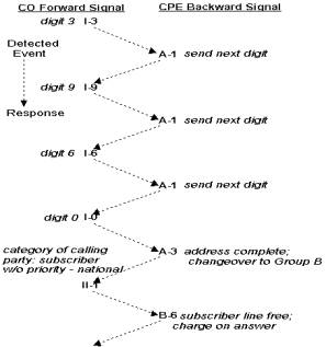
R2 MF inter-register signaling uses forward and backward compelled signaling. Simply put, with compelled signaling each signal is sent until it is responded to by a return signal, which in turn is sent until responded to by the other party. Each signal stays on until the other party responds, thus compelling a response from the other party.
Reliability and speed requirements for signaling systems are often in conflict, the faster the signaling, the more unreliable it is likely to be. Compelled signaling provides a balance between speed and reliability because it adapts its signaling speed to the working conditions with a minimum loss of reliability.
The R2 MF signal is composed of two significant events, tone-on and tone-off. Each tone event requires a response from the other party. Each response becomes an acknowledgement of the event and an event for the other party to respond to.
Compelled signaling must always begin with a Group I forward signal.
· The CO starts to send the first forward signal.
· As soon as the CPE recognizes the signal, it starts to send a backward signal that serves as an acknowledgement and at the same time has its own meaning.
· As soon as the CO recognizes the CPE acknowledging signal, it stops sending the forward signal.
· As soon as the CPE recognizes the end of the forward signal, it stops sending the backward signal.
· As soon as the CO recognizes the CPE end of the backward signal, it may start to send the next forward signal.
The CPE responds to a tone-on with a tone-on and to a tone-off with a tone-off. The CO responds to a tone-on with a tone-off and to a tone-off with a tone-on.
Refer to the following figures for more information:
There are many details about this protocol that we won’t go into but it is
certainly faster than DTMF or MF T1 robbed bit and a lot more information about the call, the called party and the caller
can go back and forth. These advantages come with quite a big implementation
price tag difference though, Since seizures and signaling, all come as compelled
tone interchanges, you need a voice resources attached to every channel. The
hardware for a 4 E1 wink start OmniBox system could go for say $11000 while an
R2 MF will require more than a $32000 investment.
ISDN PRI
The
Integrated Services Digital Network (ISDN) is a digital communications network
capable of carrying all forms (voice, computer, and facsimile) of digitized data
between switched endpoints. ISDN may use D4 SF, ESF and E1 framings but what
distinguishes ISDN from earlier protocols is signaling.
Not
only that signaling is done in an out-of-band fashion (E1 accomplished that too)
making all channels potentially “Clear”, it is that the quality of signaling
is changed to one that can convey a lot more information at a speed far beyond
that of the fastest R2 MF.
ISDN
was implemented for the T1 carrier system by using the 24th timeslot,
the first 23 are called “B channels”
(Bearer channels) while the 24th is the “D channel” (Data channel). The implementation allows the use of
one timeslot for up to 8 T1, this is called NFAS
(Non Facility Associated Signal). With the E1, no voice channel needs to
be sacrificed for signaling, since it was already out of band in the 16th
timeslot. In both cases there is a 64Kbts channel for data information.
With
ISDN, a call can be setup with information about the caller (ANI) and the called
number (DNIS) in the millisecond range. A single DTMF digit, in its shortest
version, is 50 ms plus a 50 ms space, a ten digit number requires a whole
second. Is not just faster, is 1000 times faster, such a huge difference brings
up a totally different ball game. It takes only a few milliseconds for a switch
to get the dialed digits, analyze them and, if there are no available channels
to the requested destination, it may choose not to “accept” the call. I can
even tell the reason for not accepting it. Now the seizing switch still has
plenty of time to reroute the call to alternative routing options. This opens
the concept of a channel state beyond the narrow Off hook/ On Hook scheme, there
is a whole set of possible states to a call now.
ISDN
Call Control States
Each
ISDN call that is received or generated by an application is processed through a
series of call control states. Each state represents the completion of certain
tasks and/or the current status of the call. The following table describes the
ISDN call control states, based on standard Q.931 (Layer 3).
Call
Control States
|
Call
State |
Description |
|
ACCEPTED
|
An indication to the network that the incoming
call has been accepted, but has not been connected to the end user. |
|
ALERTING
|
The destination is reached and the phone is
ringing. |
|
CONNECTED
|
An incoming or outgoing call is established.
Typically, billing begins at this point and the B channel is cut through. |
|
DIALING
|
Address and call setup information has been sent
to, and acknowledged by, the network. Call establishment is in progress. |
|
DISCONNECTED
|
The network terminates the call and the
application should drop the call. |
|
IDLE
|
A call is dropped and waiting for the application to release the call
reference number (CRN). |
|
NULL
|
No call is assigned to the device (time slot or
line). |
|
OFFERED
|
An incoming call is offered by the network. |
Here is a sequence for an inbound call:
Event: Seizure Accept Connect Caller hangs-up Call is dropped Call is released
State: Offered Accepted Connected Disconnected IDLE NULL
Now an Outbound
Event: Seizure Ringing Answer Remote hangs-up Call is dropped Call is released
State: Dialing Alerting Connected Disconnected IDLE NULL
When a call is dropped a code for the cause of dropping the call can be sent back to the other end, below a table with the coded causes.
|
Cause |
Description |
|
BAD_INFO_ELEM |
Information element nonexistent or not implemented |
|
BEAR_CAP_NOT_AVAIL |
Bearer channel capability not available |
|
CAP_NOT_IMPLEMENTED |
Bearer channel capability not implemented |
|
CHAN_DOES_NOT_EXIST |
Channel does not exist |
|
CHAN_NOT_IMPLEMENTED |
Channel type not implemented |
|
FACILITY_NOT_IMPLEMENT |
Requested facility not implemented |
|
FACILITY_NOT_SUBSCRIBED |
Facility not subscribed |
|
FACILITY_REJECTED |
Facility rejected |
|
GC_USER_BUSY |
End user is busy |
|
INCOMING_CALL_BARRED |
Incoming call barred |
|
INCOMPATIBLE_DEST |
Incompatible destination |
|
INTERWORKING_UNSPEC |
Interworking unspecified |
|
INVALID_CALL_REF |
Invalid call reference |
|
INVALID_ELEM_CONTENTS |
Invalid information element |
|
INVALID_MSG_UNSPEC |
Invalid message, unspecified |
|
INVALID_NUMBER_FORMAT |
Invalid number format |
|
MANDATORY_IE_LEN_ERR |
Message received with mandatory information element of incorrect length |
|
MANDATORY_IE_MISSING |
Mandatory information element missing |
|
NETWORK_OUT_OF_ORDER |
Network out of order |
|
NO_CIRCUIT_AVAILABLE |
No circuit available |
|
NO_ROUTE |
No route |
|
NO_USER_RESPONDING |
No user responding |
|
NONEXISTENT_MSG |
Message type nonexistent or not implemented |
|
NORMAL_CLEARING |
Call ended normally |
|
NUMBER_CHANGED |
Number changed |
|
OUTGOING_CALL_BARRED |
Outgoing call barred |
|
PRE_EMPTED |
Call preempted |
|
PROTOCOL_ERROR |
Protocol error, unspecified |
|
RESP_TO_STAT_ENQ |
Response to status inquiry |
|
SERVICE_NOT_AVAIL |
Service not available |
|
TEMPORARY_FAILURE |
Temporary failure |
|
TIMER_EXPIRY |
Recovery on timer expired |
|
UNSPECIFIED_CAUSE |
Unspecified cause |
|
WRONG_MESSAGE |
Message type invalid in call state or not implemented |
|
WRONG_MSG_FOR_STATE |
Message type not compatible with call state |
This is shown only to illustrate the superiority of ISDN technology.
SS7 Protocol
SS7 has very much the same capabilities as the ones described above but it may use a totally separate line for data information. That data line may be a full T1 a V.35 or any other fast serial link. This link may convey signaling data for many T1’s, and it is today the carrier’s favorite protocol. SS7 is not just a link but a whole network concept.
Each
signaling point in the SS7 network is uniquely identified by a numeric point
code. Point codes are carried in signaling messages exchanged between
signaling points to identify the source and destination of each message. Each
signaling point uses a routing table to select the appropriate signaling path
for each message.
There
are three kinds of signaling points in the SS7 network:
·
SSP
(Service Switching Point)
·
STP
(Signal Transfer Point)
·
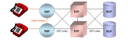
SCP
(Service Control Point)
SS7
Signaling Points
SSPs are switches that originate, terminate, or tandem calls. An SSP sends signaling messages to other SSPs to setup, manage, and release voice circuits required to complete a call. An SSP may also send a query message to a centralized database (an SCP) to determine how to route a call (e.g., a toll-free 1-800/888 call in North America). An SCP sends a response to the originating SSP containing the routing number(s) associated with the dialed number. An alternate routing number may be used by the SSP if the primary number is busy or the call is unanswered within a specified time. Actual call features vary from network to network and from service to service.
Network traffic between signaling points may be routed via a packet switch called an STP. An STP routes each incoming message to an outgoing signaling link based on routing information contained in the SS7 message. Because it acts as a network hub, an STP provides improved utilization of the SS7 network by eliminating the need for direct links between signaling points. An STP may perform global title translation, a procedure by which the destination signaling point is determined from digits present in the signaling message (e.g., the dialed 800 number, calling card number, or mobile subscriber identification number). An STP can also act as a "firewall" to screen SS7 messages exchanged with other networks.
Because
the SS7 network is critical to call processing, SCPs and STPs are usually
deployed in mated pair configurations in separate physical locations to ensure
network-wide service in the event of an isolated failure. Links between
signaling points are also provisioned in pairs. Traffic is shared across all
links in the linkset. If one of the
links fails, the signaling traffic is rerouted over another link in the linkset.
The SS7 protocol provides both error correction and retransmission capabilities
to allow continued service in the event of signaling point or link failures.
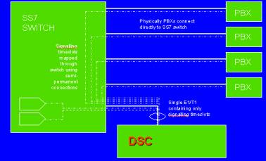
There are recent solutions that convert SS7 data stream to that ISDN PRI which is supported by OmniBox systems. The Technology is called DSC for Digital Signaling Converter from Data Kinetics.