Today a lot of advantages for digital communications can be enumerated, like:
1. Ease of multiplexing (Single media many channels)
2. Ease of signaling (On hook, Off hook, wink)
3. To join the computer hype
4. Integration of Transmission and switching
5. Signal regeneration v/s amplification
6. Performance monitorability
7. Accommodation of other services
8. Immunity to noise and interference
9. Ease of encryption.
(Ease means lower costs involved)
But the main driving force toward digital technology was, at the beginning, to multiplex and reach longer distances (points 1, 5 and 8).
Going digital didn’t come without a price tag:
1. It requires wider bands.
2. Requires time synchronization.
3. No easy conferencing.
4. Incompatibilities with analog facilities.
Most of what we will have to learn here is the related to multiplexing technology, that is the knowledge of how to have different channels of information sharing the same transmission media. There are two ways of slicing the information transmission capacity into channels, you may do time division or you may divide its inverse space, the frequency spectrum, the first choice is called Time Division Multiplexing or TDM and the second is called Frequency Division Multiplexing of FDM.
The most familiar to the common person is the FDM, because is the one used to divide the “Air” into radio or TV stations. It was also the first kind used to share a same cable for several phone conversations, like the cable under the sea. Analog TDM also existed but it shared the same problems as its counter part:
· Degradation of the signal in the repetition process needed in to compensate attenuation.
· Costs of the FDM related equipment.
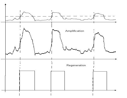
When there is information in the amplitude of a signal like in analog signals and it attenuates, say to 1/50th of its original value, to restore it you need to amplify it, this is, multiply the signal strength by a factor of 50. The only problem is noise, let us say that originally there was a 10v signal and .1v of noise, after attenuation the signal was only .5v but noise still is .1v, now you amplify and you get a 10v signal again but with 5v of noise with it. To the noise you must add linear and non linear distortions and all sorts of interference. The concept of analog signals is simple but implementations get very complicated. The digital approach solved the above problems.
Figure 1. Amplify v/s regenerate.
In the Digital approach a value is expressed not by signal strength, but as a sequence of equally strong and sized pulses, the existence or not of pulses in a sequence expresses the value. When information is not in the analogy to a physical quantity, you don’t need to amplify but you just regenerate. Let us say that we had 10v pulses that while propagating through out media they attenuate down to .5v in the presence of .1v noise. When the repeater circuit senses a pulse it won’t attempt to amplify it, but to generate a brand new 10v pulse, it won’t multiply the noise this time. You can regenerate as many times as it is need with no signal degradation. That is why every time you copy an analog recording it degrades, from here the concept of generations. A digital recording won’t degrade, you may copy a file from a floppy to a hard drive to another floppy again and again and it will always be the same.
The concepts involved here are sampling, binary numbers system, Conversion law and synchronization.
For a signal to be digitized first it must be sampled. Sampling converts a continuous signal to discrete one. The circuits that do this job are call sample and hold circuits.
Figure 2. Sample and hold
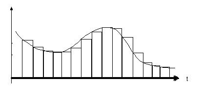
The situation might not come so clear as the frequency of the signal approaches the sampling one. Distortions known as aliasing start to show up. To select a sampling frequency the Nyquist criteria is used It says that the sampling frequency must be greater than twice the bandwidth of the signal. So if a POTS (Plain Old Telephone Service) requires a 3 to 4 KHz bandwidth a sampling rate of 8 KHz should be enough.
As we discussed earlier, one of the digital signal great advantages was that it could be regenerated. This great feature comes from the fact that the information lies in the existence or not of the signal and not in its strength. So numbers must be expressed in a sequences of YES’es and No’s. How? by using a numbering system that complies to that condition, this is the binary system. As mathematicians put it, a base 2 numbering system as opposed to familiar base 10 numbering.
Base 10 Base 2
0 0
1 1
2 10
3 11
4 100
5 101
6 110
7 111
8 1000
9 1001
As in the decimal system each digits is a power of 10 in the binary system each digit in is a power of 2 so, a number like:
10110001 = 1x27 + 0x26 + 1x25 + 1x24 + 0x23 + 0x22 + 0x21 + 1x20 = 177
128 + 0 + 32 + 16 + 0 + 0 + 0 + 1
Actually 177 means:
177 = 1x10² + 7x101 + 7x100
Very much the same thing, only that the first is expressed only using 0’s and 1’s and that could be pulse no pulse as we need for regeneration. Each digit in a binary number is called a Bit, the example above was an eight bit number. In the decimal system some powers of ten get special names, like 102 is call a hundred, 103 a thousand, 106 a million and so on, in “Computerich” some powers of 2 get special names too, an eight bit number or 28, is a Byte, 216 a Word, 232 a Double Word and there a more names. With a Byte you can count from 0 to 255, or say it has 256 = 28 possible values.
The circuits that convert signal strength of a sample into a sequence of pulses are called Analog to Digital converters or simply AD converters. Several methods have been used to accomplish this task. Early circuits used PPM or Pulse Position Modulation, but it has been the PCM or Pulse Code Modulation the one that has prevailed for its small bandwidth, noise immunity and versatility.
The two most important features in an AD is its speed and its resolution. The first determines the maximum sample rate and the second is expressed in bits and says how many different levels of signal strength will it differentiate. But there is also the issue of the “Law”, this is how the number it outputs relates to the signal strength.
The simplest example of AD converter is the one with the linear law. This AD converts the strength of the signal into a number proportional to it, this is very good for a Digital Multimeter but very bad for expressing a sound signal. The nature of sound is such that when you listen to music, the signal strength of the violin is more than a thousand times weaker than that of the Tympani, yet you hear them both. In speech some consonants are a lot weaker than the vowels, yet if you dump these consonants from a speech signal, it becomes unintelligible. If you use a Byte for expressing signal strength and set 255 to the Tympani, a violin solo would be below 1 and won’t be heard at all.
AD converters used in telephony comply to laws that distribute the available numbers according to a near logarithmic curve. They allow more numbers to the low level signals and less to the higher ones. There are two Laws used in digital telephony, the µ-Law was the first standard used by Bell Telephone in America and there is the A-Law, adopted later by the CCITT and that is used in the Europe and most of the world.
Once a signal is converted into a sequence of pulses and sent over a transmission media there is still a problem. How is the receiver to know where does the byte starts. You have two ways of dealing with this, either you include some sort of “framing mark” in the pulse stream that will hint the receiver as to which sequence of eight bit actually belong to the same byte or you send a separate pulse stream to synchronize the first.
The first approach is the one used in Digital Telephony, the second one required one cable too many. The issue of: how do you “mark” a pulse sequence? This issue follows.
The problem of introducing a “mark” in the stream has had many different approaches. Introducing pulses with different amplitudes or duration’s is a simple approach, but then, it still keeps an analog element that is no good for regeneration. The winning ticket was held by the framing pattern approach. It consisted on the introduction of a framing bit every 24 bytes or 192 bits, this was called a frame. These framing bits would present a fix pattern of:
100011011100
that would repeat every 12 frames. Each set of 12 frames is called a Super Frame (SF).
The circuit at the receiver would have to look for a match and lock a local frame frequency oscillator to that match. It is highly unlikely for the random pulses on the stream to produce a match, even if it happened, an isolated spurious match could not affect too much a locked oscillator.
Framing is independent of what kind of information goes inside the frames, but actually it was intended to convey 24 simultaneous conversations. 24 sound signals where digitized and inserted into each of the bytes in the frame, these were called time slots. Since sound for telephony had to be sampled 8000 time a second, then there had to be 8000 frames a second or (192+1)*8000 = 1544 MHz. This standard was named T1 (Trunk level1) and the equipment that converted analog lines to T1 were called Channel Banks. This kind of framing was used for the first time in AT&T D4 channel banks, that’s why today this kind framing is known as D4 or D4 SF.
T1 is also referred to as DS1 (Digital Signal level 1), this is a whole hierarchy, DS0 is the channel, DS1 is the 24 channels, DS2 is 4 DS1’s, DS3 is 28 DS1’s (must go on fiber optics) and DS4 which is 6 DM3’s.
As oscillator circuits improved their stability, there was no need for so many framing bits and another framing type was introduced that had just one framing pulse every 4 frames and the pattern was reduced to a six bit one 001011, rendering a 24 frame super frame. This type was called extended super frame or ESF. The former framing pulses were not removed from the stream but used for other purposes. These pulses became a data channel that was used for redundancy checks, alarms and end to end statistics, and the name changed to Enhanced Extended Super Frame or EESF.
As happened with TV and other communication standards, Europe came up with their own "better" system some time after the T1 was in use in the US and Canada. It is called the E1 (E for Europe, in case you haven't guessed). The E1 standard features 32 timeslots of 64Kbit/s that add up to 2.048 MHz, 30 bearer channels for voice (or whatever), one for signaling (Off Hook, On Hook, Answer supervision, etc) and one for framing. No framing bits here, the pattern (I0011011) is held by the timeslot 0 (even frames only, odd frames use these bits for other administration information). Well, something you must give Europeans, the framing concept is simpler.
Computers and normal digital circuitry work using unipolar pulses, pulses go from a 0, near ground potential, to a 1 near the power supply voltage. The problem is that unipolar pulses have a DC (Direct Current, constant value) component which implies useless energy dissipation and will not be transmitted through transformers, capacitors or radio links. When you block the DC with a capacitor, it charges to the average DC in the signal, as the proportion of 0’s to 1’s varies the DC in the capacitor “wanders”, changing the peak and valley voltages of the wave. This makes impossible to set a threshold voltage for discriminating “pulse” from “no pulse”.
Stands for Alternate Mark Inversion. From the days of the telegraph, the state with current was the “Mark” and the no current state of the line was a “Space”. Alternating the polarity of the current for successive marks avoids the DC wander. With AMI, a 0 is a no current and a 1 is a Mark, this mark, instead of having a fixed polarity, it will alternate, once positive, next negative. This will be a “bipolar” pulse stream. The waveform resulting from this approach has no DC component. Besides, the alternation becomes a redundancy parity check, since any missing 1 will cause a bipolar violation that can be readily detected.
Figure 3 Alternate Mark Inversion
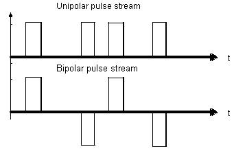
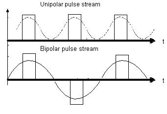
There’s another advantage to the bipolar pulse stream and it is that the bandwidth needed is cut roughly in half. The frequency of first harmonic of a uniform unipolar pulse stream of 1000 pulses/second is 1KHz. If you invert the polarity of every other pulse the first harmonic now will have only half that frequency as seen below.
The internal clock in the receiver is locked to the incoming pulse stream. If the stream is suspended the internal oscillator frequency will wander and lose its sync with the source. A long sequence of 0’s is equivalent to no signal, so in order to keep sync, a minimum amount of 1’s is required.
To provide these 1's, you could force the less significant bit in a byte to be 1 every time the rest of the bits in the byte are 0’s. This practice is called jamming, but since the 8th bit is already been used, as will become clear when we discuss signaling, it is the 7th bit the one to jam. This technique for providing the necessary 1’s is called 7th bit jamming and is the one used under the name AMI.
The plain AMI is good for voice channels but in a T1 carrier you may use the frames to convey whatever information you choose to send. If you attempt to send data in the frames, then you may no longer use jamming. To send data you need a “Clear Channel”, this is, one that would accept any combination of bits including all 0’s. So this requires a different approach. There are many solutions to this problem and they are referred to as line codes, the one known as B8ZS, that stands for Binary 8 Zero Substitution, is a common option. Every time a transmitter is about to send its 8th zero in a row, it replaces it with a pattern that includes a bipolar violation. When the receiver finds a bipolar violation, check for the pattern and replaces the correct zero value. If a transmitter is set to use a B8ZS line code, but the receiver is set for plain AMI, B8ZS patterns will be detected as bipolar violations and wrong 1’s will show up.
Besides digitized voice, a channel must also convey off hook/on hook information. An analog line does this with the Loop Current, which is the DC component of the sound signal. When you go off hook, the Loop Current is established, when you connect to your party, the polarity of the current is reversed, if the party hangs up, you recover the original polarity, when you hang up the Loop Current goes to 0. This is called signaling. Now, how do you provide for signaling in the Digital world? …Next Class
This concept comes from nature, locked oscillators are all around us. Is happens every time you have an oscillating system, like a pendulum, loosely coupled to another. The effect is that, in time, they end up synchronizing, this, in more rigorous terms, that their frequencies become multiples. The time in which this “sync” happens depend on how strong is the coupling and how far off the nearest multiple is to their ‘natural’ (unlocked) frequency.
When a man plays a trumpet (a trombone, a tuba, etc.) his oscillating libs lock to the air column vibrations in the instrument. All the player has to do is tighten his lib muscles so that its natural frequency, when he blows, comes near to one the air column resonant frequencies. Any inaccuracy in the tightening of his libs will result in a lock to the wrong harmonic of the tube and… it really sounds awful.
Another example of natural locking... Have you ever wonder why is it that you see only one face of the moon, how come the rotation frequency is EXACTLY equal to its orbital period? Well… these two oscillatory motions are locked, it probably took some time, but they finally became locked.
Now, back to our discussion of electronic locked oscillators for communication purposes. Local frame oscillators, mentioned above, are very stable and accurate quartz oscillators that deviate very little from the incoming frequency. Even very weak coupling would be enough to produce a lock under these conditions, but yet, very strong coupling methods have been devised, capable of producing a lock in very little time. The method is called Phase Lock Loop (PLL). The phase of a sample from the incoming pulse stream is subtracted to that of the internally generated one, if a result different than zero is rendered, a correcting signal is sent to the oscillator until there’s no difference. This method produces a very strong lock.