ECEF Calculation for Range and Bearing
By Armando Rodriguez
(This is not a reproduction from some Geosciences textbook, equations here were derived by its author to cope with the limitations of the simple precision floating point arithmetic library available for the Texas Instrument's DSP TMS320F2812. )
To test a TCAS, signals must be fed to it as if they were comming from its own antenas on the aircraft. These signals must pretend a scenario where intruder aircrafts will be entering its surveilled air space. The motion of every aircraft in the scenario is calculated using ECEF coordinates in order to accurately calculate the ranges an bearing that TCAS should be sensing, yet their positions must be reported in Geodetic coordinates.
The expressions for the position vector R
in the Earth Centered Earth Fixed Cartesian coordinate system (ECEF) in terms of
the geocentric coordinates are:
X = R cos(lng) cos(ltc) (1)
Y = R sin(lng) cos(ltc) (2)
Z = R sin(ltc) (3)
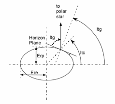
Where R is the modulus of vector R, or the distance from an intruder aircraft to the center of the Earth, the lng is the longitude and ltc is the geocentric latitude. This latitude is the angle of R to the equatorial plane, but there it can’t be measured directly. The only measurable angle is the one between the earth rotation axis and the gravitational normal, by, for instance, measuring the angle the Polar star rises above the horizon. This angle is called the geodetic latitude (ltg), if the Earth where a perfect sphere, there would be no distinction between both definitions, but the Earth is slightly flattened so as to make them differ a little more than 11 minutes around the 45 degrees of latitude.
In Aerospace, intruder latitudes are expressed according to the geodetic definition, so, in order to use the above expressions we need to transform it. The relation between de Geodetic (ltg) and Geocentric (ltc) latitudes goes as:
ltc = atan((Erp/Ere)2 tan(ltg)) (4)
The components of relative position vector Rio (hereon, vectors will be noted in italics) of an intruder I from our own plane O, can be expressed as:
Xio = RI cos(lngI) cos(ltcI) – RO cos(lngO) cos(ltcO) (5a)
Yio = RI sin(lngI) cos(ltcI) – RO sin(lngO) cos(ltcO) (5b)
Zio = RI sin(ltcI) – RO sin(ltcO) (5c)
Where RI and RO are, respectively, the distances of the Own and Intruder planes to the center of the Earth. Lat’s and lng’s follow the same convention.
The problem with the above expressions is that they are unsuitable for a 32 bit floating point arithmetic implementation as the one in the DSP library. The DSP's single precision arithmetic handles numbers only up to 7 significant figures. For planes within a nautical mile, these operands may differ only in the last two digits, allowing for errors in the thousand of feet. Yet if we manipulate the expressions, for instance, in (4) by adding and subtracting RO cos(lngI) cos(ltcI), we get:
Xio = (RI-RO) cos(lngI) cos(ltcI) + RO(cos(lngI) cos(ltcI) - cos(lngO) cos(ltcO)) (7a)
Applying the same method to Y and Z we get.
Yio = (RI-RO) sin(lngI) cos(ltcI) + RO(sin(lngI) cos(ltcI) - sin(lngO) cos(ltcO)) (7b)
Zio = (RI-RO) sin(ltcI) + RO (sin(ltcI) - sin(ltcO)) (7c)
Since:
RI = Eri + hI (8)
RO = Ero + hO (9)
Where Eri and Ero are vectors from the center of Earth to the projection of the plane position on the surface of the Earth ellipsoid for the Intruder and Own position respectively. Its Cartesian coordinates may be expressed as.
Xio = (Eri-Ero) cos(lngI) cos(ltcI) + Ero(cos(lngI) cos(ltcI) - cos(lngO) cos(ltcO)) (10)
Yio = (Eri-Ero) sin(lngI) cos(ltcI) + Ero(sin(lngI) cos(ltcI) - sin(lngO) cos(ltcO)) (11)
Zio = (Eri-Ero) sin(ltcI) + Ero (sin(ltcI) - sin(ltcO)) (12)
hI and hO are the altitude vectors which are not radial but follow the gravitational direction, therefore the latitude should be the geodetic:
hio = (hI-hO) cos(lngI) cos(ltgI) + hO(cos(lngI) cos(ltgI) - cos(lngO) cos(ltgO)) (13)
hio = (hI-hO) sin(lngI) cos(ltgI) + hO(sin(lngI) cos(ltgI) - sin(lngO) cos(ltgO)) (14)
hio = (hI-hO) sin(ltgI) + hO (sin(ltgI) - sin(ltgO)) (15)
Using the ellipsoidal approximation, the Earth radius becomes a function of the ltc.
Er(lat) = 1/Ö (cos2 (ltc)/Ere2 + sin2(ltc)/Erp2) (16)
Or, with fewer operations to code:
Er(lat) = Ere/Ö (1 + K sin2(lat)) (17)
Where K = (Ere2 – Erp2)/Erp2, or in terms of the Earth eccentricity e : K = e2/(1-e2).
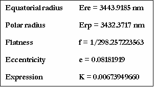
Geodesic constants in accordance to WGS 84 are:

The Range Rio is:
Rio = Ö(Xio2 + Yio2 + Zio2) (18)
The Bearing B is the angle of the projection of Rio on the plane tangent to the Own position respect to the true north. We are going to need unit vectors along the true North and the true East. The true North unit vector Un can be obtained deriving R with respect to lat in equations (1) to (3), dividing by its modulus and evaluating for the own plane position.
Unx = - cos(lngO) sin(latO) (19)
Uny = - sin(lngO) sin(latO) (20)
Unz = cos(latO) (21)
The true East unit vector is same but deriving respect to lng.
Uex = - sin(lngO) (22)
Uey = cos(lngO) (23)
Uez = 0 (24)
The Bearing B may now be expressed as:
B = atan( Ue · Rio/Un · Rio) (25)
For Un · Rio > 0 or else:
B = p + atan( Ue · Rio/Un · Rio) (26)
The slant or horizontal range (not used in the DSP software) would be:
___________________________________________
Rh = Ö ((Ue · Rio * Ue · Rio ) + (Un · Rio *Un · Rio )) (27)
These equations render valid values for R and B for all geodesic coordinates skipping the singularity on Un · Rio = 0, for which B=+/-p/2.