This study was done to estimate the necessary gate voltage stability for biaasing the so called “Pixel LNA” This is a HEMT based microwave Low Noise Amplifier. This paper shows expertise in the the physics of semiconductor devices and circuitry.
The pixel LNA is an InP HEMT that stands for Indium Phosphide High Electron Mobility Transistor. For the present analysis this device is just a field effect transistor (FET), because the only characteristic relevant to the issues to be discussed is that transconductance g (dId/dVgs), which for all FET's is linearly dependent to Vgs at constant Vds. Since voltage gain in an FET amplifier is proportional to transconductance, then:
G = K(Vgs – Vt) Eq 1
Where K is just a constant, Vt is the threshold voltage and G is the voltage gain. An amplifier with N identical stages has a total gain Gt of:
Gt = GN Eq 2
If gain changed in dG the change in the total gain would be:
dGt = N G(N-1) dG Eq 3
If Vgs voltage where to be set with an error dVgs then it would introduce a change dG:
dG = K dVgs Eq 4
Its effect on the total gain:
dGt = N G(N-1) K dVgs Eq 5
To obtain an expression in relative terms, we can divide both members by Gt and:
dGt/Gt = N K dVgs /G = N dVgs/(Vgs-Vt) Eq 6
If the input and output resistance sare equal the total power gain Wg equals the voltage gain squared and so and increment dGt will cause an increment in power gain dWg as:
dWg = 2Gt dGt Eq 7
Dividing into Wt to go relative:
dWt/Wt = 2dG/Gt Eq 8
Finally
dWt/Wt = 2N dVgs/(Vgs-Vt) Eq 9
In our case, N = 5
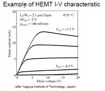
Threshold voltages for GaAs HEMT’s range in the volts as can be seen below.

Figure 1
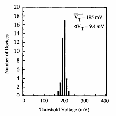
However, the InP HEMT’s seem to show much lower Vt values, as reported by the Center for Compound Semiconductor Microelectronics, Coordinated Science Laboratory and Department of Electrical and Computer Engineering of the University of Illinois, 208 N. Wright St., Urbana, IL 61801, USA
Figure 2.

For InP HEMT’s the ratio dVgs/(Vgs-Vt) go in the .range of 0.001 for dVgs of 0.1 mv. So evaluating Eq 9:
dWt/Wt ~ 10* 0.0001/0.01 = 1%
Figure1
Concluding that a gate voltage stability of 1 mv guarantees a power gain within 1%.