 shift corrections for the difference in RF paths. This correction is calculated
by comparing the phases P12 to P32 when irradiating from 2 and similarly,
somehow, it also finds a correction for P42.
shift corrections for the difference in RF paths. This correction is calculated
by comparing the phases P12 to P32 when irradiating from 2 and similarly,
somehow, it also finds a correction for P42.By Armando Rodriguez
After what was expect to be a perfect calibration, still the simulated intruders were not showing up at the position they were set to be. This was figured out to be consequence of TCAS periodical antenna calibration. This paper describes how the TCAS correction can be calculated from the observed deviations and the way IQ tables have to be altered to properly compensate this effect.
When TCAS is transmitting to the TPG_E, it is the antenna
simulator that absorbs its power. TCAS periodically calibrates; this is, it will
update the phase shift corrections for the difference in RF paths. This correction is calculated
by comparing the phases P12 to P32 when irradiating from 2 and similarly,
somehow, it also finds a correction for P42.
With a perfect antenna simulator this wouldn’t pose a problem, since it wouldn’t add any phase shift to the one introduced to the external cables and connectors. Unfortunately, it is not perfect and TCAS will compensate these asymmetries too.
The TPG_E transmitters have been calibrated to simulate intruder signal as close as possible to the theoretical phase differences. In order for TCAS to calculate the right intruder bearings, the phases must include the phase shifts it is expecting after the “imperfect” antenna it sensed when calibrating.
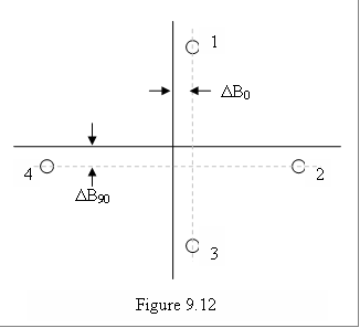
For measuring how much is this over correction TCAS has introduced, a scenario is created with four static Mode C intruders with 3 nautical mile range and with bearings at 0º, 90º, 180º and 270º. Typically, errors introduced by asymmetries in the antenna simulator are like the ones shown in Figure 9.12, where DB0 and DB90 are usually about 5º.
Math for the compensation of TCAS correction to the antenna simulator
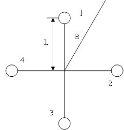
 Let
K be:
K = 2p L/l (1)
Then the phases relate to the intruder bearing as;
f12 = K(cos(B) - sin(B)) (2)
f 32 = K(cos(B) + sin(B)) (3)
f 42 = 2Ksin(B) (4)
Or that B relates to the phases as:
B = cos-1((f12 - f32)/2K) (5)
B = sin-1((f12 + f32)/2K) (6)
B = sin-1(f42 /2K) (7)
The paths conveying the signals to the phase detector introduce phase differences of df12, df32 and df42. We will assume these to be small as to approximate the sine to the angle.
For B = 0, these phase differences will introduce the effect of deviating the reading in DB. If calculated from (7):
DB0 = df42/2K (8)
For B = p/2, since f12 = f32, then from (5)
DB90 = (df12 - df32)/2K (9)
But from (6):
(f12 + f32)/2K = sin(B) (10)
Differentiating:
(df12 + df32)/2K = cos(B)dB (11)
For B = p/2, cos(B) = 0, then:
df12 = -df32 (12)
Combining (8), (9) and (12) we obtain the compensations for the top antenna.
df42 = 2DB0K (13)
df12 = -df32 = DB90 K (14)
For the bottom antenna, the reference becomes 4 instead of 2, the compensations are then:
df24 = -2DB0K (15)
df14 = -df34 = DB90 K (16)
Now, our antenna simulator is introducing these small path differences when TCAS is calibrating. TCAS calibration will compensate for all path differences, not only those internal to TCAS or the external ones, like cable and connectors, but will also compensate for the antenna simulator’s asymmetries. Our transmitter inserts into these paths its signal, that have been calibrated to have the theoretical phase difference. In order simulate what TCAS would be receiving from an antenna with the such asymmetries, we need to modify our signals to match that imperfection.